Introduction to the Arduino guide series
The basics of Arduino programming: Loops, conditions, objects, inputs & outputs
In this lesson, we discuss the basics of Arduino programming to help you understand the basic concepts of the Arduino language: loops and conditionals, classes and objects, inputs and outputs.
This is the last article of the Getting Started series. We’re going to complete our discussion of the basics of Arduino programming.
In the previous lesson, you learned about things like variables, functions, and loops.
Today, you will build on this knowledge and learn three new important concepts:
- The programming structures that allow your Arduino (and any computer) to make decisions and repeat instructions.
- Classes and objects that allow us (the programmers) to create reliable programs that resemble concepts from our real-world experiences.
- Inputs and outputs that enable us to connect external components like buttons and lights, to the Arduino.
Let’s begin with loops (structures we use to repeat instructions) and conditionals (structures we use for decision making).
Loops and conditionals
Conditionals are useful when you want to change the flow of executing in your sketch. Loops are useful when you want to repeat a block of code multiple times.
Very often, these two work together; that’s why I discuss them here in the same section.
Let’s start with a conditional. Imagine you have a red light and a green light. You want to turn the green light on when you press a button and the red light on when you leave the button not pressed.
To make this work, you can use a conditional.
conditional: “if..else”
The most common of these is the if...else statement. Using pseudo code (that is, a program written in English that looks a bit like a real program), you would implement this functionality like this:
if (button == pressed)
{
	green_light(on);
	red_light(off);
} else
{
	red_light(on);
	green_light(off)
}
loop: “while”
while(button_is_pressed)
{
	make_annoying_noise;
}
Easy!
loop: “do_while”
You can do the same thing but do the check of the condition at the end of the block instead of the start. This variation would look like this:
do
{
	make_annoying_noise;
} while(button_is_pressed)
loop: “for”
If you know how many times you want to repeat code in a block, you can use the for structure. Let’s say you want to blink a light 5 times.
Here’s how to do it:
for (n = 1 to 5)
{
	Turn light on;
	Turn light off;
}
Your light will turn on and then off 5 times. Inside the curly brackets, you will also have access to the n variable, which contains the number of a repeat at any given time. With is, you could insert a conditional so that you leave the lights on before the last loop ends:
for (n = 1 to 5)
{
	Turn light on;
	if (n < 5) then Turn light off;
}
In this variation, the light will only turn off if the n variable is less than 5.
conditional: “switch”
Another useful conditional is the switch. If you have a variable, like button_pressed, that can take a few valid values; you can do something like this with it:
switch (button_pressed)
{
	case 1:
		Blink light one time;
		break;
	case 2:
		Blink light two times;
		break;
	case 3:
		Blink light three times;
		break;
	default:
		Don’t blink light;
}
The switch statement will check the value stored in the button_pressed variable. If it is 1, it will blink the light once, if it is 2, it will blink the light twice, and if it is 3, it will blink three times. If it is anything else, it won’t blink the light at all (this is what the “default” case is).
The button_pressed variable can be an integer and could be taking it values from a membrane keypad, like this one:
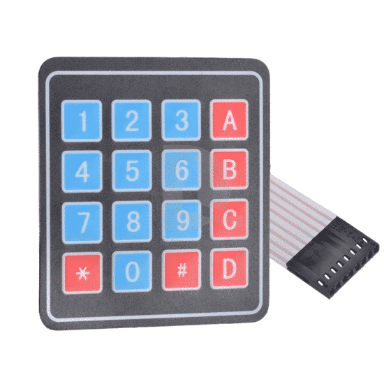
A membrane keypad can be used to provide input to your sketch.
For now, don’t worry about how this keypad works; this is something you will learn later. Just imagine that when you hit a key, a number comes out.
Also, notice the keyword “break”? It will cause the execution of the sketch to jump out of the block of code that is between the curly brackets. If you remove all the “break” statements from your sketch and press 1 on the keypad, then the sketch will cause the light to blink once, then twice, and then three times as the execution will start in the first case clause, and then move into the rest.
Classes and objects
You now know that the Arduino language is actually C++ with a lot of additional support from software, the libraries which were mentioned earlier, that makes programming easy. It was also said that C++ is an object-oriented programming language.
Let’s have a closer look at this feature and especially how it looks like in Arduino code.
Object-orientation is a technique for writing programs in a way that makes it easier to manage as they grow in size and complexity. Essentially, a software object is a model of something that we want the computer (or an Arduino) to be able to handle programmatically.
Let me give you an example. Imagine that you have a robotic hand. The arm only has one finger and can rotate by 360 degrees. The finger can be open or closed. You can model this hand in an object-oriented way like in this pseudo-code:
class robotic_hand
{
	//These variables hold the state of the hand
	bool finger;
	int rotation;

	//These variables change the state of the hand
	function open_finger();
	function close_finger();
	function rotate(degrees);

	//These variables report the state of the hand
	function bool get_finger_position();
	function int get_rotation_position();
}
Can you understand what this code does? I am creating a model of the hand and giving it the name robotic_hand. The keyword “class” is a special keyword so that the compiler understands my intention to create a model.
Inside the class, I define three kinds of components for the model (=class). First, a couple of variables to hold the current state of the hand. If the hand is in an open position, the boolean variable finger will be true. If the hand is rotated at 90 degrees, the integer variable rotation will contain 90.
The second set of components are special functions that allow me to change the status of the hand. For example, if the hand is currently open and I want to close it so that it can pick up an object, I can call the close_finger() function. If I want to rotate it at 45 degrees, I can call rotate(45).
Finally, the third set of components are functions that allow me to learn about the status of the hand. If I want to know if the hand is opened or closed, I can call get_finger_position(), and this function will respond with true or false.
The names are up to me to choose so that their role is clear. A class hides within it components such as these, so the programmer can think more abstractly about the thing they are working with, instead of the implementation details.
Let’s say now that you would like to use this class in your sketch. Here is an example of how you would do it in Arduino:
#include <Robot_hand.h>

Robot_hand robot_hand();

void setup(){
}

void loop(){
	robot_hand.open_finger();
	robot_hand.rotate(45);
	robot_hand.close_finger();
}
You would start by importing the Robot_hand library, which contains the class you just created into your Arduino sketch. You do this with the include statement in the first line of your sketch.
In the second line, you create an object based on the Robot_hand class. Think about this for a few moments: a class contains the blueprints of an object but is not an object; it is the equivalent of a blueprint for a house, and the house itself. The blueprint is not a house, only the instructions for building a house. The builder will use the blueprint as the instructions to build a house.
Similarly, the robot hand class definition is only the instructions that are needed for building the robot hand object in your sketch. In the second line of this example sketch, we are defining a new object build based on the instructions in the Robot_hand class, and we give it the name robot_hand(). The object’s name cannot be the same as the name of the class, that is why it starts with a lowercase r.
In the loop() function, we can call the object’s functions to make the robot hand move. We can open it using robot_hand.open_finger() and close it using robot_hand.close_finger(). Notice that these instructions start with the name of the object, robot_hand, followed by a dot, then followed by the name of the function we want to call, close_finger().
This is called “dot notation”, and is very common throughout most object-oriented programming languages.
There’s a lot more to learn on this topic, but to get started with Arduino programming, this level of basic understanding of object orientation can take you a long way.
Inputs and outputs
Inputs and output are a fundamental feature of the microcontroller. You can connect devices to special pins on your Arduino, and read or change the state of these pins through special instructions in your sketch.
There are two kinds of input and output pins on an Arduino: digital and an analog.
Let’s have a look at them going forwards.
Digital pins
Digital pins are useful for reading the state of devices like buttons and switches or controlling things like relays and transistors or LEDs. These examples have one thing in common: they only have two possible states.
A button can be either pressed on not pressed. A switch can be on or off. A relay can be energized or not.
If in your sketch, you want to know the state of a button, you can connect it to a digital pin. You can wire it up so that when the button is pressed, a 5V voltage is read by the connected digital pin, and that is reported as “high” to your sketch.

A button like this one is a digital device. Connect it to a digital pin.
Let’s suppose that you connected a button to a digital pin on your Arduino, as I show in this schematic:
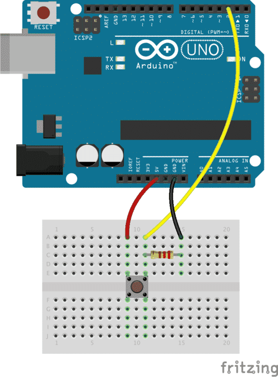
A button is connected to digital pin 2. There is also a 10KΩ resistor that conveys a 0V signal to pin 2 when the button is not pressed.
When you press the button, the voltage conveyed by the yellow wire to digital pin 2 is 5V, equivalent to “logical high.” This happens because when the button is pressed, internally, the red wire coming from the 5V source on the Arduino is connected electrically to the yellow wire that goes to pin 2.
When the button is not pressed, the voltage at pin 2 is 0V, equivalent to “logical low.” This happens because of the resistor in the schematic. When the button is not pressed, the yellow wire is connected to the GND pin on the Arduino, which is at 0V; thus, this level is transmitted to pin 2.
You can read the state of the button in your Arduino sketch like this:
int buttonState = 0;

void setup() {
	pinMode(2, INPUT);
}

void loop(){
	buttonState = digitalRead(2);
	if (buttonState == HIGH)
	{
		//Do something when the button is pressed
	} else
	{
		//Do something else when the button is not pressed
	}
}
First, create a variable to hold the state of the button.
Then, in the setup() method, tell the Arduino that you will be using digital pin 2 as an input.
Finally, in the loop(), take a reading from digital pin 2 and store it in the buttonState variable.
We can get the Arduino to perform a particular function when the button is in a specific state by using the if conditional structure.
What about writing a value to a digital pin? Let’s use an LED as an example. See this schematic:
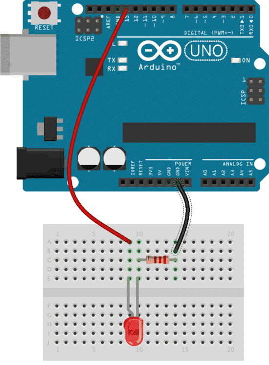
An LED is connected to digital pin 13. A 220Ω resistor protects the LED from too much current flowing through it.
In this example, we have a 5mm red LED connected to digital pin 13. We also have a small resistor to prevent burning out the LED (it is a “current limiting resistor”). To turn the LED on and off, we can use a sketch like this:
void setup()
{
	pinMode(13, OUTPUT);
}

void loop()
{
	digitalWrite(13, HIGH); // turn the LED on (HIGH is the voltage level)
	delay(1000); // wait for a second
	digitalWrite(13, LOW); // turn the LED off by making the voltage LOW
	delay(1000); // wait for a second
}
Just like the button example, first, we must tell the Arduino that we wish to use digital pin 13 as an output. We do this in the setup() function with pinMode(13,OUTPUT). In the loop() function, we use the digitalWrite function to write logical HIGH and LOW to digital pin 13. Each time we change the state, we wait for 1000ms (=1 second). The Arduino has been configured to translate logical HIGH to a 5V signal, and logical LOW to a 0V signal.
Analog pins
Let’s move to analog now. Analog signals on microcontrollers is a tricky topic. Most microcontrollers can’t generate true analog signals. They tend to be better at “reading” analog signals. The ATMEGA328P, which is used on the Arduino Uno, simulates analog signals using a technique called Pulse Width Modulation. The technique is based on generating a pattern of logical HIGHs and LOWs in a way that generates an analog effect to connected analog devices.
Let’s look at an example. We’ll take the same LED circuit from the digital pins section and make it behave in an analog way. The only difference in the schematic is that you have to change the wire from digital pin 13 to go to digital pin 9 instead. Here is the new schematic:
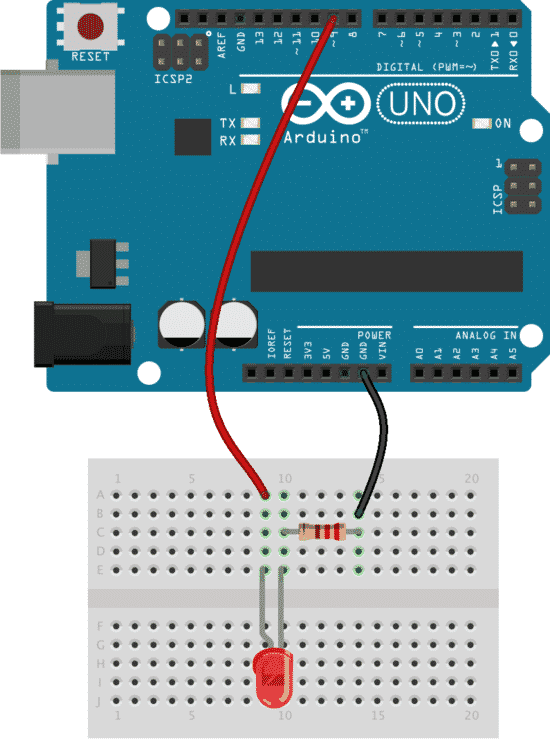
An LED is connected to digital pin 9. A 220Ω resistor protects the LED from too much current flowing through it.
In this example, change the red wire to go to digital pin 9 instead of 13. We do this because we want to make the LED fade on and off via pulse width modulation. Pin 9 has this capability, but pin 13 does not.
We have to switch the controlling pin because we want to simulate an analog signal through the use of Pulse Width Modulation (PWM). Only a few of the pins on an Arduino can do this. One of these pins is 9, which we are using in this example.
Before showing you how to write an analog value to a PWM pin, look at this YouTube video to see what the end result is like.
Here is the sketch to make the LED fade on and off:
void setup()
{
}

void loop()
{
	for (int fadeValue = 0 ; fadeValue <= 255; fadeValue += 5)
	{
		analogWrite(9, fadeValue);
		delay(30);
	}
}
In the middle of the loop() function, you will find a reference to the analogWrite function. This function takes two arguments: the PIN and an 8-bit PWM value.
In the example, the variable fadeValue contains a number that changes between 0 and 255 in hops of 5 each time it is analogWrite is called because it is inside a for loop. When fadeValue is at 0, then the analogWrite function keeps the output at pin 9 to 0V. When fadeValue is at 255, then analogWrite keeps the output at pin 9 to 5V. When fadeValue is at 127, then analogWrite keeps the output at pin 9 at 0V for half of the time and 5V for the other half.
Because the ATMEGA is a fully digital IC, it simulates analog by just switching between digital high and low very quickly. For the LED to be brighter, we give analogWrite a larger value, which simply increases the amount of time that the pin stays at logical high versus logical low.
What about reading the state of an analog device? Let’s use a potentiometer as an example. This example combines an LED with a potentiometer.
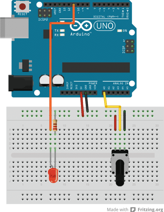
The potentiometer is this diagram has its middle pin (signal) connected to analog pin 0.
In this example, when you turn the knob of the potentiometer in one direction, the LED becomes brighter. When you turn it towards the other direction, it becomes fainter.
We want to make the LED brighter when we turn the knob of the potentiometer towards one direction and fainter when we turn it towards the other. To make this happen, we will both get an analog reading of the state of the potentiometer, and produce PWM output for the LED.
In this video, you can see how the circuit works:
Here is the sketch:
void setup()
{
	pinMode(9, OUTPUT);
}

void loop()
{
	int potValue = analogRead(A0);
	int brightness = map(potValue,0,1023,0,255);
	analogWrite(9,brightness);
}
In the setup function, we set pin 9 to output because this is where we have connected the LED. Pins are inputs by default, so we don’t have to set analog pin 0 to be an input explicitly.
In the loop function, we get a reading from analog pin 0 (its name is “A0”) and store it in a local integer variable, potValue. The function analogRead returns an integer with a range from 0 to 1024. Remember from the earlier example that the PWM function can only deal with the value from 0 to 255. This means that the value we store in potValue will not work with analogWrite.
To deal with this, we can use the Arduino “map” function. It takes a number that lies within a particular range and returns a number within a new range. So in the second line of the loop function, we create a new local integer variable, brightness. We use the map function to take the number stored in potValue (which ranges from 0 to 1023) and output an equivalent number that ranges from 0 to 255.
Notice that the parameters of the map function match the range of potValue and brightness? The conversion calculation is done for you, easy!
Analog read and write are easy once you understand the implications of the available resolution and Pulse Width Modulation. With what you already know, you will be able to work with a multitude of devices using the circuits from the examples in this section.
For example, if you would like to use a membrane potentiometer link this one:
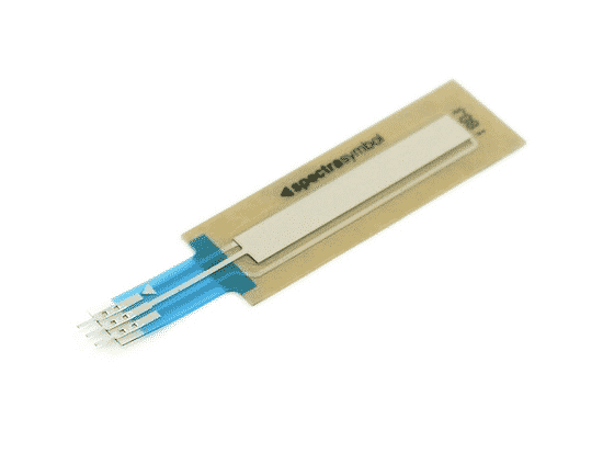
A membrane potentiometer. Electrically it works like a normal rotary potentiometer.
Just remove the rotary potentiometer from the example circuit and replace it with the membrane potentiometer. You will be able to control the brightness of the LED by sliding your finger up and down the membrane.
That wraps up this introductory course on the Arduino!
I hope you enjoyed these articles and that you learned something new.
Ready for some serious Arduino learning?
Start right now with Arduino Step by Step Getting Started
This is our most popular Arduino course, packed with high-quality video, mini-projects, and everything you need to learn Arduino from the ground up.
New to the Arduino?
Arduino Step by Step Getting Started is our most popular course for beginners.
This course is packed with high-quality video, mini-projects, and everything you need to learn Arduino from the ground up. We'll help you get started and at every step with top-notch instruction and our super-helpful course discussion space.
Jump to another article
1. What is the Arduino?
2. Common Arduino boards
3. Types of hardware that you can connect to an Arduino board
4. The Arduino programming environment
5. Arduino libraries and how to install them
6. The basics of Arduino programming: program structure, functions, variables, operators
7. The basics of Arduino programming: Loops, conditions, objects, inputs & outputs
We publish fresh content each week. Read how-to's on Arduino, ESP32, KiCad, Node-RED, drones and more. Listen to interviews. Learn about new tech with our comprehensive reviews. Get discount offers for our courses and books. Interact with our community. One email per week, no spam; unsubscribe at any time

